EUROplast “Plastics” Issue 10/98

To the point
Optimal sprue position and gate shape for plastic parts
Long-term, often very expensive practical experience shows that most errors in tool design are made in the area of injection. Cost-intensive corrections can be avoided if a design checklist is systematically worked through before the tool is designed. The practitioner with the relevant professional experience certainly knows and takes into account all the constructive aspects mentioned here. Nevertheless, banal errors still occur in day-to-day business, the number of which can be reduced by consistently working with the questions compiled here (Table 1). If just one of these questions is answered with “no”, this can lead to subsequent, expensive changes to the tool. The checklist can also be incorporated into a failure mode and effects analysis (FMEA) for tool design. The individual problems are explained below.

economics
If rework is required to remove the sprue, this must be taken into account when calculating the part price. The most common self-separating sprue system with only one parting level that can be operated fully automatically is the tunnel sprue. The optimal gate shape with regard to gentle material processing is the bar gate, which, however, is material and post-processing intensive and increases manufacturing costs due to the extension of the cooling time.
Optical aspects
Often the optimal gate location from a technical point of view cannot be realized because the part has to meet demanding optical requirements at this point. In some circumstances, the use of a needle gate nozzle may be considered.
Mold filling
The relationship between flow path and wall thickness must enable complete mold filling. In addition to complex simulation software, the flow curves offered by raw material manufacturers have proven useful here. These — possibly supplemented with the graphical filling image method — allow an initial reliable check of the mold filling as long as the geometries are relatively simple with uniform wall thicknesses.
Weld lines
Weld lines should be located in areas of the injection molded part where they cannot lead to strength problems. For complex molded parts, a mold filling study to find the weld seam areas can be worthwhile. A cascade gate system can avoid weld lines, but this significantly increases tooling costs.
Air pockets
It must be ensured that the air in the cavity can escape. We recommend air grooves on all ejectors as well as a circumferential ventilation groove around the entire tool cavity, which is connected to the outside. Ejectors are the best form of ventilation because they clean themselves through their movement. In contrast, sintered inserts or capillary inserts have the disadvantage that they quickly become clogged due to outgassing from the material, thereby affecting production reliability.
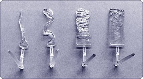
Free jet bonding
To avoid a free jet, the injection must be carried out against a tool wall and not into the free cavity. This is actually a banal error, but one that is nevertheless frequently observed (Figure 1). Although the free jet formation can be mitigated by injecting with a profile, this modification of the injection should be reserved for optimizing the process and should not be used to conceal tool errors. If necessary, the tool must be supplemented with an auxiliary core in the mold. This may possibly be withdrawn during the reprint phase.
Shear heating
The shearing of the thermoplastic material during injection must not lead to extreme heating of individual tool parts. To avoid high temperatures, temperature control channels should be provided near the gate. If it is justifiable with the tool contour and function, a temperature control hole should be provided with a separate connection opposite the injection point, if possible, so that the shear heat can be specifically dissipated here. In principle, there must be a temperature control hole in the injection area of hot runner nozzles in order to be able to dissipate the inevitable excess heat from the electrically heated nozzle.
Shear stress
The gate geometry (e.g. tunnel gate) must not lead to such a high shear stress that the processed material is damaged. Basically, the bleed should therefore be made as large as possible. It may also be possible to split a gate into two or more gates to reduce shear. The formation of a weld seam between the cuts must be taken into account. Developments in the hot runner sector, especially in externally heated systems, now also allow the processing of relatively temperature-sensitive materials. Another option that is still rarely used are liquid-tempered hot runner systems.
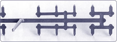
Balanced sprue system
For multiple tools or parts with multiple gates, the gating system must of course be balanced. If this is not possible, a mold filling study must be carried out to determine graduated distributor cross sections (Figure 2). In general, a naturally balanced sprue system should be used — regardless of whether it is hot or cold — and only in exceptional cases should balancing be carried out using differentiated distributor cross sections, since the viscosity of the plastic melt depends on the shear that occurs and the temperature. This means that the balancing is only exact in one point, namely the calculated point. If the processing parameters are subsequently corrected, a correction of the cross sections is usually also unavoidable.
Balanced sprue system
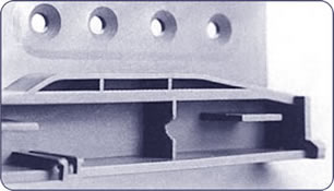
Hesitation effect
To avoid freezing of the flow front due to the delay effect (hesitation effect), the mold must be filled from large wall thicknesses towards small wall thicknesses. Thin-walled areas near the gate (e.g. film hinge) should be avoided. The old rule of plastic component construction of preferring uniform wall thicknesses is justified here. With different wall thicknesses, the melt only flows along the path of least resistance, i.e. in the direction of the greater wall thickness. However, the melt then remains on the parts of the smaller wall thicknesses until sufficient pressure has built up. The shear rate approaches zero due to the standstill of the mass and the melt front freezes due to its intrinsic viscosity (Figure 3).
Reprint
To avoid voids, sink marks, etc., sufficient pressure must be ensured. The sprue position should therefore be chosen so that you are spraying onto a thick wall that is prone to sink marks. Another possibility is to introduce flow aids between the sprue and mass accumulations to ensure the supply of additional pressure.
Default
By optimally choosing the sprue position (e.g. injection of a ruler on the narrow side), distortion can be largely avoided. Especially with fiber-reinforced materials, but also with semi-crystalline thermoplastics without reinforcement, it is important to take the question of potential distortion into account when selecting the correct injection point. Often several cuts or a film sprue have the effect of reducing distortion.
Pictures: Europlast Ep-Kunststofftechnik GmbH
author
Dipl.-Ing. Elmar Nachtsheim, born in 1959, trained as a toolmaker before working as a designer at Zeller Plastik KG, Zell/Mosel. After studying plastics technology at Darmstadt University of Applied Sciences, he was responsible for the injection molding technology division at Formplast-Reichel GmbH, Besigheim. Since 1998 he has been managing director of Europlast Ep-Kunststofftechnik GmbH, Ilsfeld.
more comments


