Plastic injection molding and ultrasonic welding of technical plastic parts. From the idea to the design and mold construction to the finished molded part.
Oct. 2021 – 16 Oct. 2021, Friedrichshafen Exhibition Center
Until shortly before the start of the trade fair, it was unclear whether Fakuma could take place due to the Corona infection situation. We were very pleased that the decision was made to hold the event. Despite the stricter hygiene regulations, interested parties and exhibitors decided to attend the trade fair.
The number of visitors was manageable, but we were still able to have some good conversations. Personal exchange is and remains very important in our view. We are confident that next year’s trade fair can take place as usual.
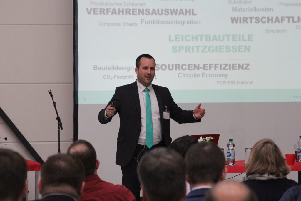
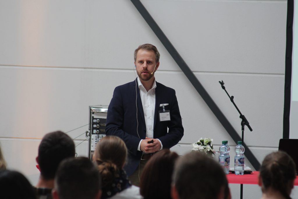
On November 18, 2016, a top-class training event took place with the 3rd EUROplast Technology and Innovation Day.
The speed at which new products are created is dizzying, but it will never again be as slow as it is today. Product innovations must be implemented before the competition. Innovative products can be sold at high prices; if the product arrives too late, the competition is often already there. We want to look into the future with you, deepen the tried and tested and learn new things.
Education is our greatest raw material in Europe, which is otherwise so resource-poor.
On November 18, 2016, a top-class training event took place with the 2nd EUROplast Innovation Day.
Join us on the exciting path to new products: We want to look into the future and will discuss everything from the design of material compositions, plastic-friendly constructions, new manufacturing processes, organic sheets for weight reduction with high strength, CT measurement and new simulation options to innovative surface technologies . Deepen the tried and tested and experience new things.
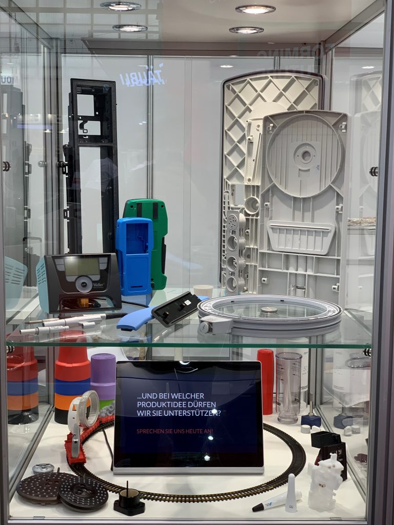
Innovative metal replacement with high-precision plastic parts made of PBT/ASA
When designing a new rotating viewing window for demanding applications in mechanical engineering, an intelligent choice of materials and tool design was required. A tool concept with a tunnel connection and symmetrical sprue distributor as well as sophisticated temperature control was designed and implemented.
The material matrix is intended to help developers who are not native to the plastics industry narrow down the right material. The matrix is deliberately kept simple, but is intended to help avoid major wrong decisions.
Practice has shown that new developments often take wrong paths when it comes to material selection, which are difficult to correct later. If a new product is created, the materials must be largely narrowed down at an early stage of construction, on which, for example, strength calculations or shrinkage are based. Some properties are provided with averaged real values, others only with school grades in order to be able to compare (1: high value / 6: lowest value)
If the raw material price is considered too late because the material was selected based on purely technical aspects, this can endanger an entire project or at least delay it enormously. However, prices are subject to a wide range of fluctuations, especially for standard plastics. Shown here is a snapshot of medium quality, with purchase quantities of around 1000 kg (as of September 2001).
In addition to calculating its own weight, the density of the material is also included in the calculation, since the volume of a plastic part is predetermined and the weight is only calculated using the specific weight. Here, looking at the volume price is an interesting statement.
Strength here means the tensile strength, knowing the fact that plastic components are primarily calculated according to the maximum elongation. This means that you define the environmental influences and then look in the tables for the strengths that you can expect the component to have in order not to exceed the maximum limit elongation.
The level of stress to which a component is exposed is crucial for its temperature resistance. It is also important how long a component is exposed to high temperatures. The values given here are average values of the usage temperature over a medium exposure time and serve as a guide only.
It is important for the designer to know how far the material flows in the mold. Average flow lengths with 2 mm component thicknesses are mentioned here. It is important to know that the flow paths increase disproportionately with thicker walls. Furthermore, in every material group there are also types with better and worse flow properties. And lastly, it must be mentioned that hot runner technology with multiple connections makes it possible to produce parts with a high wall thickness-flow path ratio.
For processing shrinkage during injection molding, only average values are given for a wall thickness of 2 — 3 mm and optimal part processing, which are based on years of experience. Due to tool temperatures that deviate from the manufacturer’s specifications, as well as inadequate temperature control channels in the tool and extreme cycle times, the real shrinkage values can deviate significantly from the values stated here. For this reason, the information provided by raw material manufacturers often covers a wide range.
The draft angles are important for removing the components from the mold without drawing marks. Due to the different shrinkage of the materials, the required demoulding angles also vary. Furthermore, thin walls require larger demolding trays than thicker walls. VDI level 30 corresponds to a medium structure with a roughing depth of 3.5 μm, although the tool should be designed with VDI level 33 due to the somewhat reduced image.
The average cavity pressure is, on the one hand, a calculation variable for the design of the injection molding machine, where strong fluctuations can occur depending on the geometry of the component, and on the other hand, the demolding forces also increase as the cavity pressure increases. The number and design of the ejectors must be adapted to these forces.
Impact strength is an important aspect for the suitability of plastic components for everyday use. In addition, the structural design contributes significantly to the durability of a component after impact stress. The influence of water absorption in polyamide and the general possibility of impact modification with, for example, elastomer modifiers should be mentioned here.
The chemical resistance of a plastic is a very complex topic because, in addition to the large number of chemical substances, their concentration and the ambient temperature also play a major role. In addition, most common chemicals are mixtures of a variety of individual substances. This means that when assessing chemical resistance you have to go through long lists of substances and the substances with which the component later comes into contact are often not tested or these substances are difficult to determine. In general and very simply, one can say: Amorphous plastics (mostly transparent plastics, if not colored) have poor chemical resistance. Partially crystalline plastics (mostly opaque plastics, if not colored) have good chemical resistance.
Apart from special processing processes (with very fast cooling speeds), all amorphous plastics are more or less transparent and all semi-crystalline plastics are opaque and translucent if the wall thickness is small. An exception here, however, is ABS, which is opaque although amorphous because it has been copolymerized from different raw materials, which influences the refraction of light. Basically, it should be noted that the dimensional requirements are often too high for plastic parts. However, it is often possible to cope with larger tolerances through a plastic-friendly design.
Optimal sprue position and gate shape for plastic parts
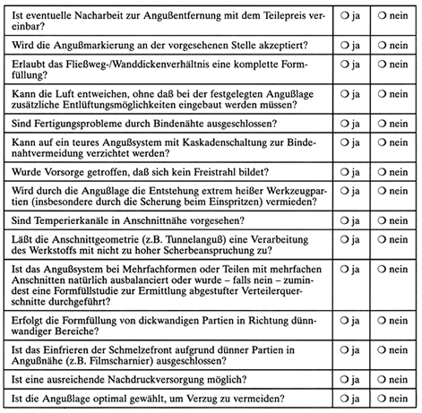
Long-term, often very expensive practical experience shows that most errors in tool design are made in the area of injection. Cost-intensive corrections can be avoided if a design checklist is systematically worked through before the tool is designed. The practitioner with the relevant professional experience certainly knows and takes into account all the constructive aspects mentioned here. Nevertheless, banal errors still occur in day-to-day business, the number of which can be reduced by consistently working with the questions compiled here (Table 1). If just one of these questions is answered with “no”, this can lead to subsequent, expensive changes to the tool. The checklist can also be incorporated into a failure mode and effects analysis (FMEA) for tool design. The individual problems are explained below.
economics
If rework is required to remove the sprue, this must be taken into account when calculating the part price. The most common self-separating sprue system with only one parting level that can be operated fully automatically is the tunnel sprue. The optimal gate shape with regard to gentle material processing is the bar gate, which, however, is material and post-processing intensive and increases manufacturing costs due to the extension of the cooling time.
Optical aspects
Often the optimal gate location from a technical point of view cannot be realized because the part has to meet demanding optical requirements at this point. In some circumstances, the use of a needle gate nozzle may be considered.
Mold filling
The relationship between flow path and wall thickness must enable complete mold filling. In addition to complex simulation software, the flow curves offered by raw material manufacturers have proven useful here. These — possibly supplemented with the graphical filling image method — allow an initial reliable check of the mold filling as long as the geometries are relatively simple with uniform wall thicknesses.
Weld lines
Weld lines should be located in areas of the injection molded part where they cannot lead to strength problems. For complex molded parts, a mold filling study to find the weld seam areas can be worthwhile. A cascade gate system can avoid weld lines, but this significantly increases tooling costs.
Air pockets
It must be ensured that the air in the cavity can escape. We recommend air grooves on all ejectors as well as a circumferential ventilation groove around the entire tool cavity, which is connected to the outside. Ejectors are the best form of ventilation because they clean themselves through their movement. In contrast, sintered inserts or capillary inserts have the disadvantage that they quickly become clogged due to outgassing from the material, thereby affecting production reliability.
Free jet bonding
To avoid a free jet, the injection must be carried out against a tool wall and not into the free cavity. This is actually a banal error, but one that is nevertheless frequently observed (Figure 1). Although the free jet formation can be mitigated by injecting with a profile, this modification of the injection should be reserved for optimizing the process and should not be used to conceal tool errors. If necessary, the tool must be supplemented with an auxiliary core in the mold. This may possibly be withdrawn during the reprint phase.
Figure 1: Injection into the free cavity leads to the formation of a free jet instead of a melt front
Shear heating
The shearing of the thermoplastic material during injection must not lead to extreme heating of individual tool parts. To avoid high temperatures, temperature control channels should be provided near the gate. If it is justifiable with the tool contour and function, a temperature control hole should be provided with a separate connection opposite the injection point, if possible, so that the shear heat can be specifically dissipated here. In principle, there must be a temperature control hole in the injection area of hot runner nozzles in order to be able to dissipate the inevitable excess heat from the electrically heated nozzle.
Shear stress
The gate geometry (e.g. tunnel gate) must not lead to such a high shear stress that the processed material is damaged. Basically, the bleed should therefore be made as large as possible. It may also be possible to split a gate into two or more gates to reduce shear. The formation of a weld seam between the cuts must be taken into account. Developments in the hot runner sector, especially in externally heated systems, now also allow the processing of relatively temperature-sensitive materials. Another option that is still rarely used are liquid-tempered hot runner systems.
Balanced sprue system
For multiple tools or parts with multiple gates, the gating system must of course be balanced. If this is not possible, a mold filling study must be carried out to determine graduated distributor cross sections (Figure 2). In general, a naturally balanced sprue system should be used — regardless of whether it is hot or cold — and only in exceptional cases should balancing be carried out using differentiated distributor cross sections, since the viscosity of the plastic melt depends on the shear that occurs and the temperature. This means that the balancing is only exact in one point, namely the calculated point. If the processing parameters are subsequently corrected, a correction of the cross sections is usually also unavoidable.
Balanced sprue system
Figure 2: If the sprue system is not naturally balanced, attention must be paid to graduated distributor cross sections
Hesitation effect
To avoid freezing of the flow front due to the delay effect (hesitation effect), the mold must be filled from large wall thicknesses towards small wall thicknesses. Thin-walled areas near the gate (e.g. film hinge) should be avoided. The old rule of plastic component construction of preferring uniform wall thicknesses is justified here. With different wall thicknesses, the melt only flows along the path of least resistance, i.e. in the direction of the greater wall thickness. However, the melt then remains on the parts of the smaller wall thicknesses until sufficient pressure has built up. The shear rate approaches zero due to the standstill of the mass and the melt front freezes due to its intrinsic viscosity (Figure 3).
Figure 3: The freezing of the melt due to the hestitation effect leads to incomplete mold filling in the thin-walled area
Reprint
To avoid voids, sink marks, etc., sufficient pressure must be ensured. The sprue position should therefore be chosen so that you are spraying onto a thick wall that is prone to sink marks. Another possibility is to introduce flow aids between the sprue and mass accumulations to ensure the supply of additional pressure.
Default
By optimally choosing the sprue position (e.g. injection of a ruler on the narrow side), distortion can be largely avoided. Especially with fiber-reinforced materials, but also with semi-crystalline thermoplastics without reinforcement, it is important to take the question of potential distortion into account when selecting the correct injection point. Often several cuts or a film sprue have the effect of reducing distortion.
Pictures: Europlast Ep-Kunststofftechnik GmbH
author
Dipl.-Ing. Elmar Nachtsheim, born in 1959, trained as a toolmaker before working as a designer at Zeller Plastik KG, Zell/Mosel. After studying plastics technology at Darmstadt University of Applied Sciences, he was responsible for the injection molding technology division at Formplast-Reichel GmbH, Besigheim. Since 1998 he has been managing director of Europlast Ep-Kunststofftechnik GmbH, Ilsfeld.
Education is our greatest raw material in Europe, which is otherwise so resource-poor.
The first EUROplast Innovation Day took place on November 8th, 2013.
Join us on the exciting path to new products: from design to material selection — biopolymers are also presented — to plastic-friendly construction and innovative welding technology. Optimized processing methods and cost savings, for example through the use of stack molds, are explained and discussed in greater depth.
This website uses cookies for analysis and statistics. Cookies help us to improve the user-friendliness of our website. By clicking “Accept”, you agree to the use of all cookies.
This website uses cookies to improve your experience while you navigate through the website. Of these, the cookies that are classified as necessary are stored on your browser as they are essential for the working of basic functionalities of the website. We also use third-party cookies to help us analyze and understand how you use this website. These cookies are only stored in your browser with your consent. You also have the option to refuse these cookies. However, refusing some of these cookies may affect your browsing experience.
Necessary cookies are absolutely essential for the website to function properly. This category only includes cookies that ensures basic functionalities and security features of the website. These cookies do not store any personal information.
Analytical cookies are used to understand how visitors interact with the website. These cookies help provide information on metrics the number of visitors, bounce rate, traffic source, etc.
Cookie
Dauer
Beschreibung
brz-firstVisit
never
Brizy sets this cookie to store on the first visit.
brz-lastVisit
never
Brizy sets this cookie to store the last visit.
brz-pagesViews
never
Brizy sets this cookie to store which page was visited first.
brz-pagesViewsInSessionTimeLine
never
Brizy sets this cookie to store and track interaction.
brz sessions
never
Brizy sets this cookie to store ad display frequency.
brz-showedPopupsInSessionTimeLine
never
Brizy sets this cookie to store performed actions on the website.